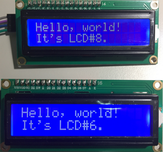
Arduino UNO R3 以I2C介面並聯兩個 1602A LCD
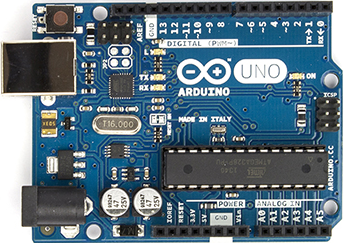
1. Arduino UNO R3 * 1
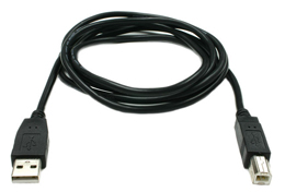
2. USB 傳輸線 * 1 (一端是A Type,一端是B Type接頭)
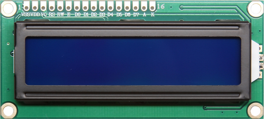
3. Hitachi HD44780U 1602A LCD * 2
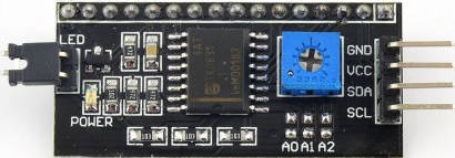
4. Arduino I2C 轉接板 * 2
1. 安裝Arduino IDE (本例使用的版本是v1.6.13),官方載點:https://www.arduino.cc/en/Main/Software

2. 第一次將Arduino板接上電腦時,需要安裝Driver,可自行選擇驅動程式路徑,Driver的預設路徑在"C:\Program Files (x86)\Arduino\drivers\"底下(需先安裝IDE才會有Driver),驅動完成後裝置管理員會多一個Com Port出來。
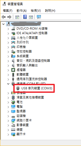
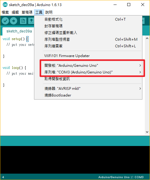
3. 第一次啟動Arduino IDE,要先設定開發板的種類與序列埠埠號,開發板選擇Uno,序列埠則視系剛剛驅動程式裝好後新增出來的埠號是多少來做設定,本例是COM3。
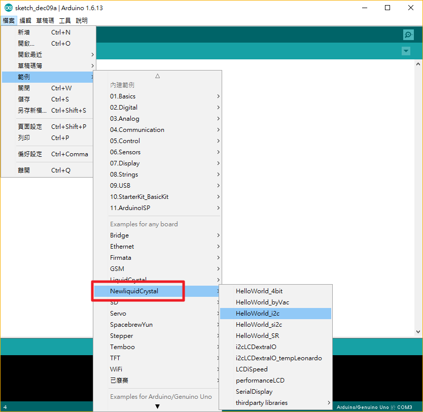
4. 安裝 NewliquidCrystal 函式庫,載點1:https://bitbucket.org/fmalpartida/new-liquidcrystal/downloads,載點2:https://github.com/smiron/WarehouseHumidityController,下載後將「NewliquidCrystal_1.3.4.zip」解壓縮,將「NewliquidCrystal」資料夾放至「C:\Program Files (x86)\Arduino\libraries\」中,重新開啟IDE後可於「檔案 -> 範例」中看到「NewliquidCrystal」。
1. 將 I2C 轉接板焊至1602a LCD後面,如下圖:(如對焊接不在行也可購買已焊好的)
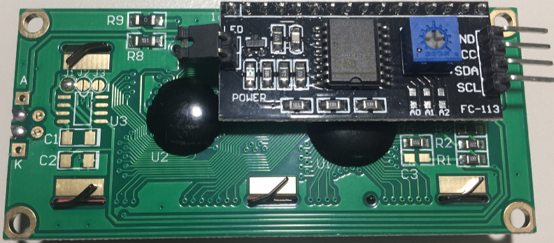
2. 由於我們要使用I2C介面,並將兩塊做並聯,所以其中有一塊需要設定位址,通常此I2C轉接板預設位址為0x27,也有少部分是0x3F,設定位址的方式為透過I2C轉接板上的A0, A1, A2短路與否來做設定,預設值為全部開路,可參考下表作設置:
| A0 | A1 | A2 | |
| 0x27 | 0 | 0 | 0 |
| 0x26 | 1 | 0 | 0 |
| 0x25 | 0 | 1 | 0 |
| 0x24 | 1 | 1 | 0 |
| 0x23 | 0 | 0 | 1 |
| 0x22 | 1 | 0 | 1 |
| 0x21 | 0 | 1 | 1 |
| 0x20 | 1 | 1 | 1 |
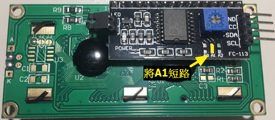
本例的另一張卡片設定為0x25,如下圖所示:(大家一定很奇怪,為何不用0x26,原因是本人手拙,在焊A0點時焊壞了,所以只好使用A1來短路了,還好A1沒出槌,不然就只剩A2了,那我就更緊張了...T_T,當然,本人還是有羞恥心的,當然不會將焊壞的那張照片PO上來,所以使用好的那一張用畫的來做說明)
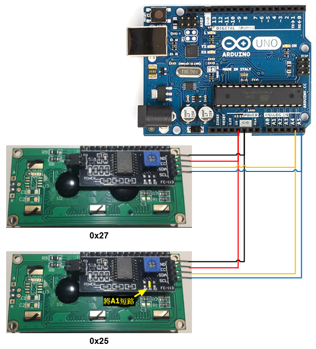
3. 接下就是要與Arduino UNO R3板子座連接囉~接線圖如下:(GND - GND, 5V - VCC, A4 - SDA, A5 - SCL)
程式碼參考https://arduino-info.wikispaces.com/LCD-Blue-I2C的範例做修改,內容如下:
/* YourDuino.com Example Software Sketch
 16 character 2 line I2C Display
 Backpack Interface labelled "A0 A1 A2" at lower right.
 ..and
 Backpack Interface labelled "YwRobot Arduino LCM1602 IIC V1"
 MOST use address 0x27, a FEW use 0x3F
 terry@yourduino.com */

/*-----( Import needed libraries )-----*/
#include <Wire.h>  // Comes with Arduino IDE
// Get the LCD I2C Library here:
// https://bitbucket.org/fmalpartida/new-liquidcrystal/downloads
// Move any other LCD libraries to another folder or delete them
// See Library "Docs" folder for possible commands etc.
#include <LiquidCrystal_I2C.h>

/*-----( Declare Constants )-----*/
/*-----( Declare objects )-----*/
// set the LCD address to 0x27 for a 16 chars 2 line display
// A FEW use address 0x3F
// Set the pins on the I2C chip used for LCD connections:
//                    addr, en,rw,rs,d4,d5,d6,d7,bl,blpol
//LiquidCrystal_I2C lcd1(0x27, 2, 1, 0, 4, 5, 6, 7, 3, POSITIVE);  // Set the LCD#1 I2C address

const int lcdCount = 8;
LiquidCrystal_I2C lcd[lcdCount] =
{
  LiquidCrystal_I2C(0x20, 2, 1, 0, 4, 5, 6, 7, 3, POSITIVE),
  LiquidCrystal_I2C(0x21, 2, 1, 0, 4, 5, 6, 7, 3, POSITIVE),
  LiquidCrystal_I2C(0x22, 2, 1, 0, 4, 5, 6, 7, 3, POSITIVE),
  LiquidCrystal_I2C(0x23, 2, 1, 0, 4, 5, 6, 7, 3, POSITIVE),
  LiquidCrystal_I2C(0x24, 2, 1, 0, 4, 5, 6, 7, 3, POSITIVE),
  LiquidCrystal_I2C(0x25, 2, 1, 0, 4, 5, 6, 7, 3, POSITIVE),
  LiquidCrystal_I2C(0x26, 2, 1, 0, 4, 5, 6, 7, 3, POSITIVE),
  LiquidCrystal_I2C(0x27, 2, 1, 0, 4, 5, 6, 7, 3, POSITIVE)
};

const int cols = 16;
const int rows = 2;

void setup()
{
  InitialLCD();
}

void loop()
{

}

void InitialLCD()
{
  for(int i=0; i<lcdCount; i++)
  {
    lcd[i].begin(cols, rows);   //LCD initialization and associated HW.

    // ------- Quick 3 blinks of backlight  -------------
    for(int j = 0; j< 3; j++)
    {
      lcd[i].backlight();
      delay(250);
      lcd[i].noBacklight();
      delay(250);
    }

    lcd[i].backlight();   //Switch-on the LCD backlight.

    lcd[i].clear();   //清除 LCD 畫面
    lcd[i].setCursor(0,0);  //將游標移至第一行第一列
    lcd[i].print("Hello, world!");
    delay(500);
    lcd[i].setCursor(0,1);  //將游標移至第一行第二列
    lcd[i].print("It's LCD#" + String(i+1) + ".");
  }
  delay(1000);
}